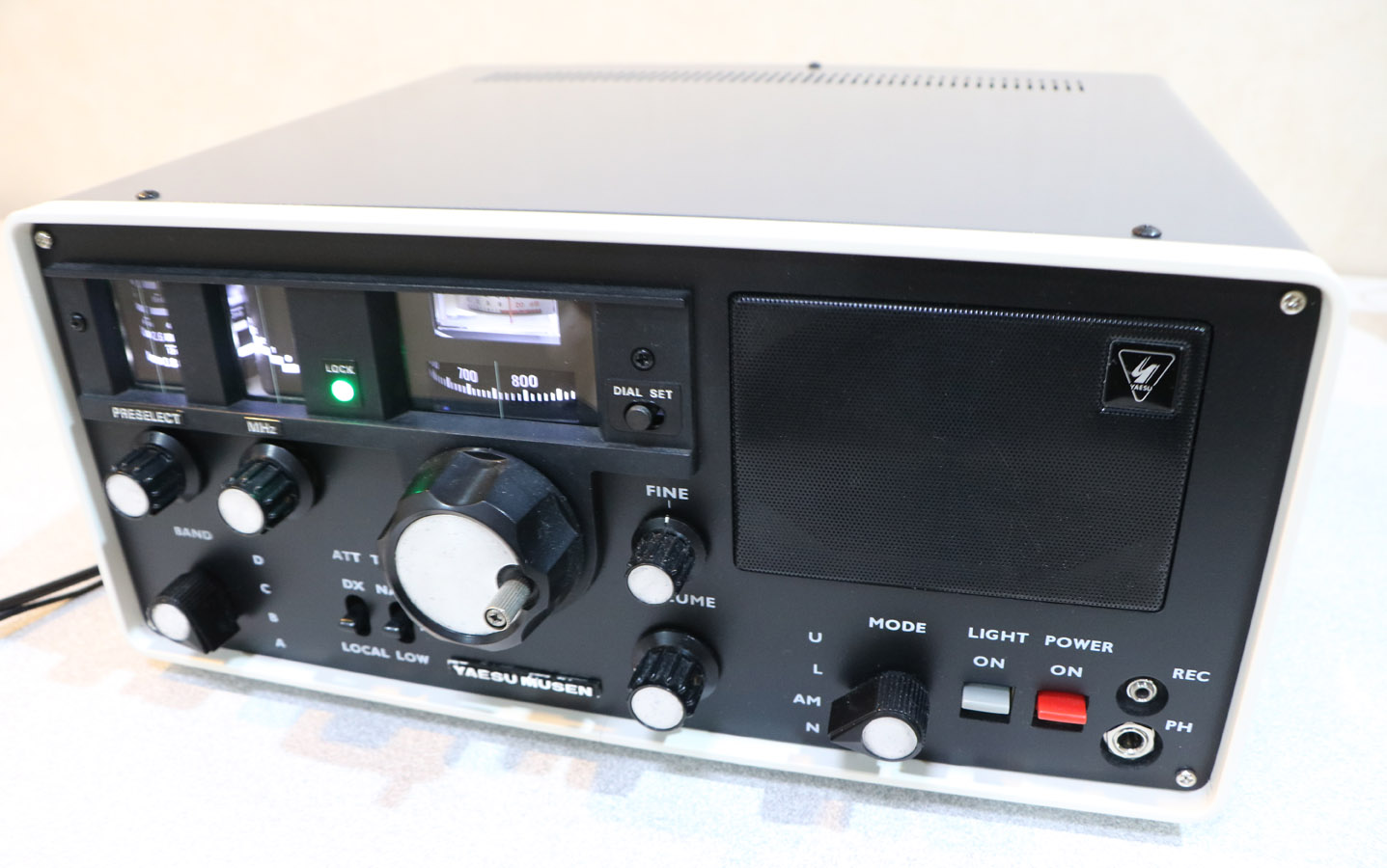
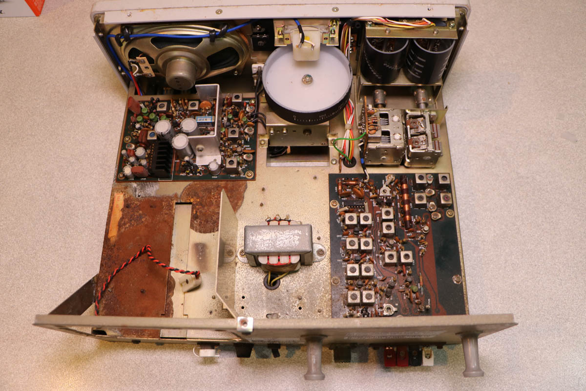
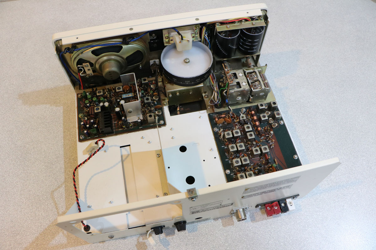
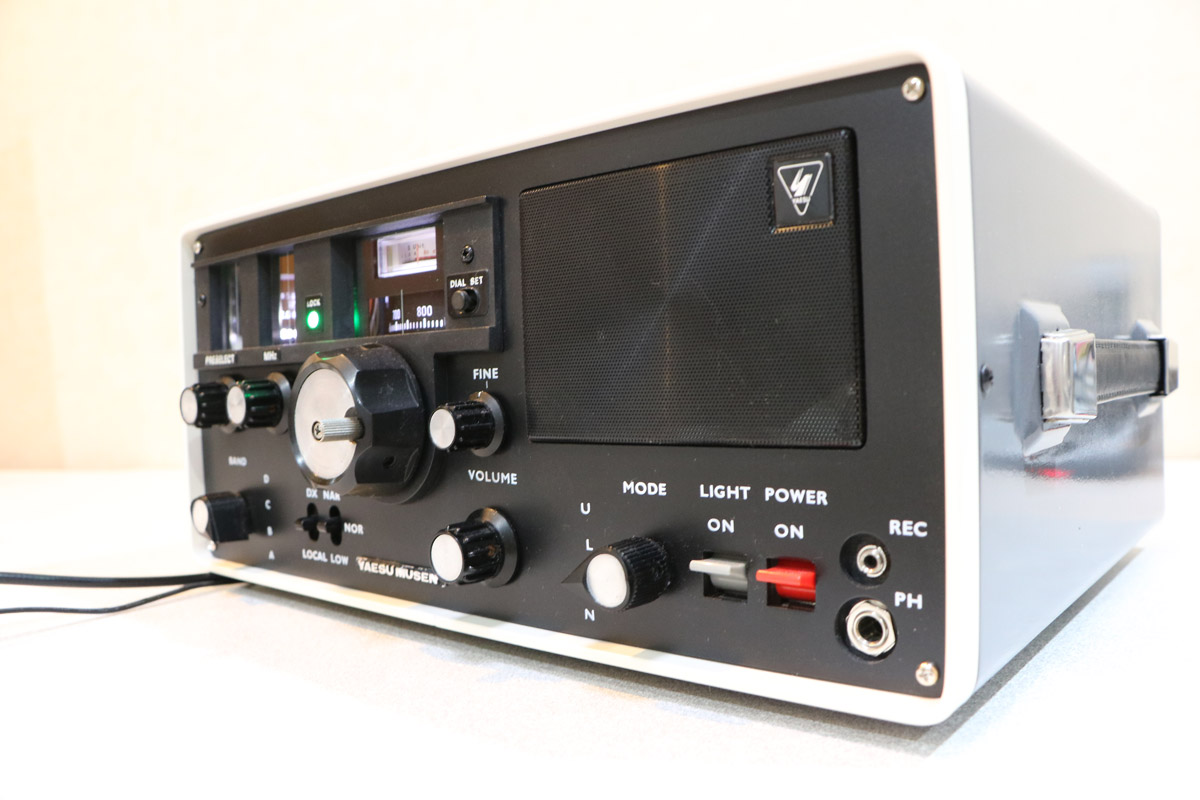
AMATEUR RADIO PROJECTS

SELECT A PROJECT...  or scroll down

ICOM IC-22 IC-30

SOFTWARE

IC-7300 S METER

DELPHI CI-V

IC-7300 TFT Display

TUNERS

TAIT T500

TAIT T198

JUST FOR FUN

YAESU FRG-7

ICOM RADIOS

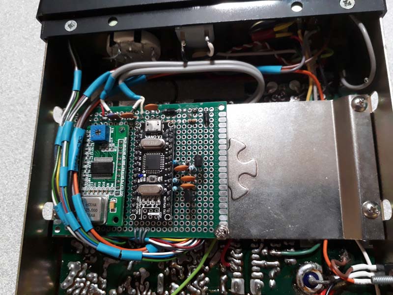
The modifications to Icom transceivers started with an IC-22A and the replacement of the Xtals with a DDS. Next was an IC-22S with a very temperamental PLL so a different DDS was employed for that. Next on the list was a UHF IC-30A. 
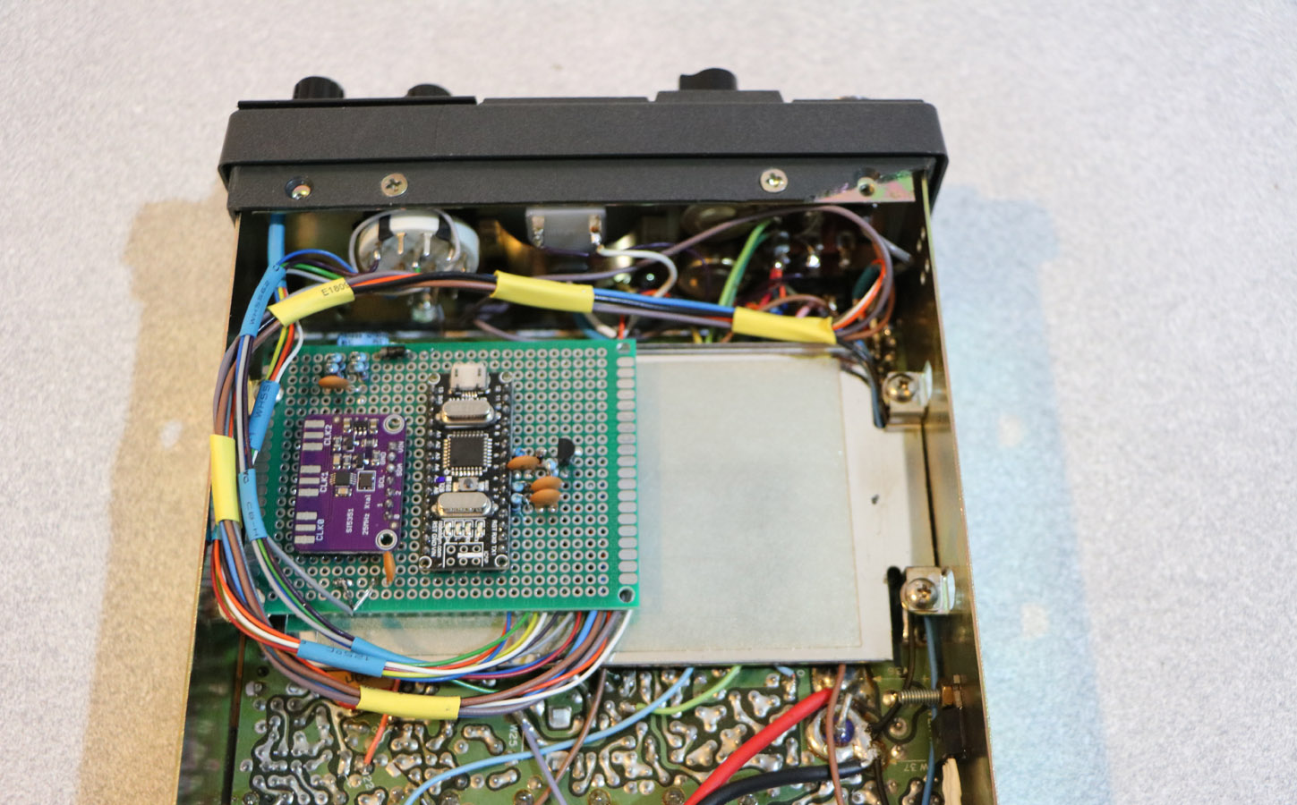
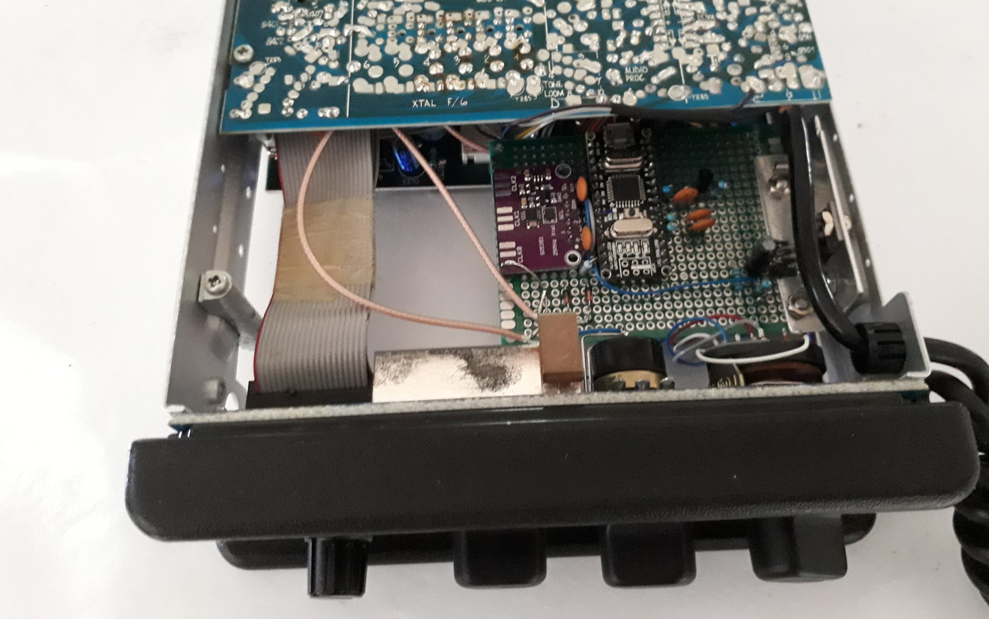
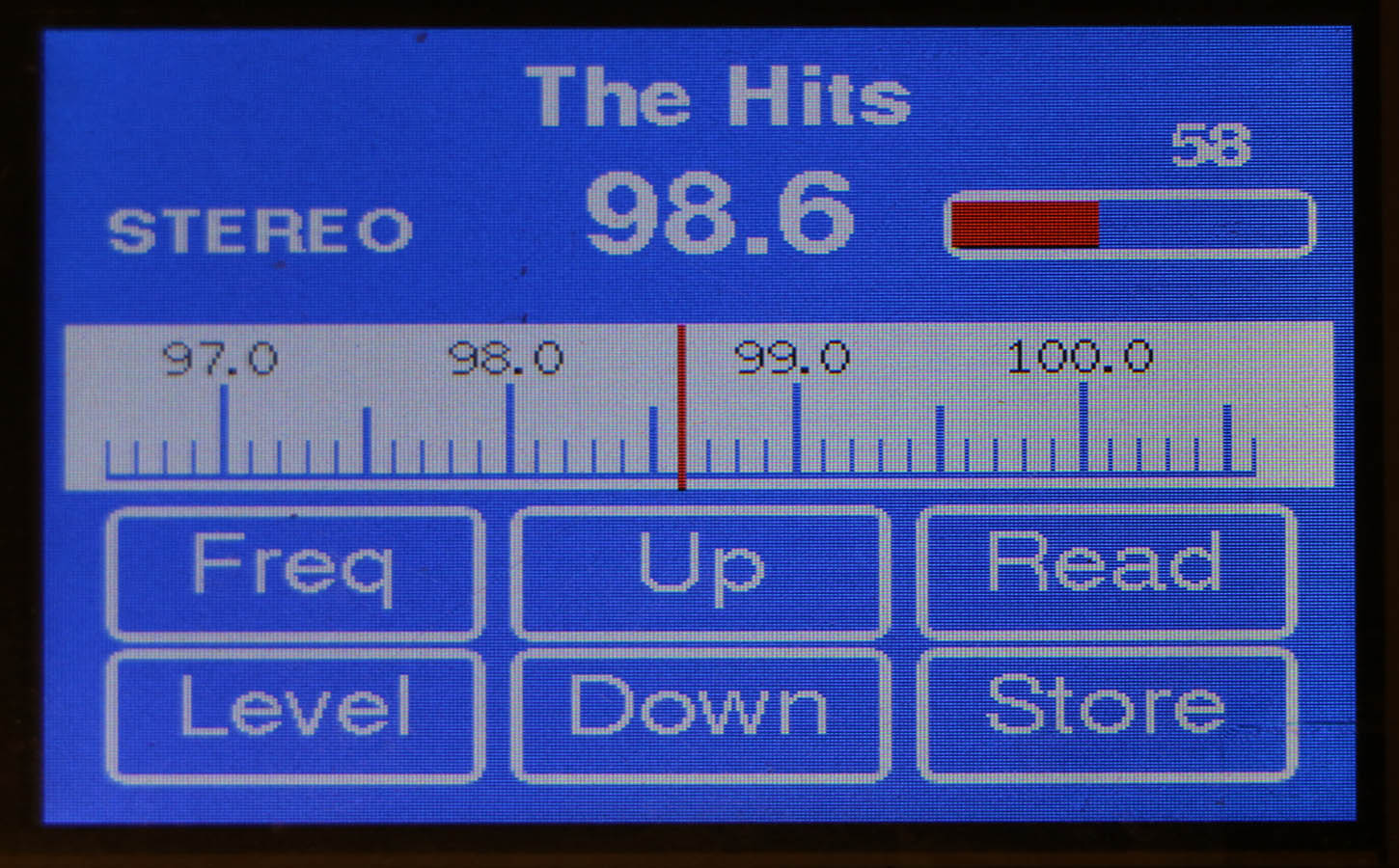
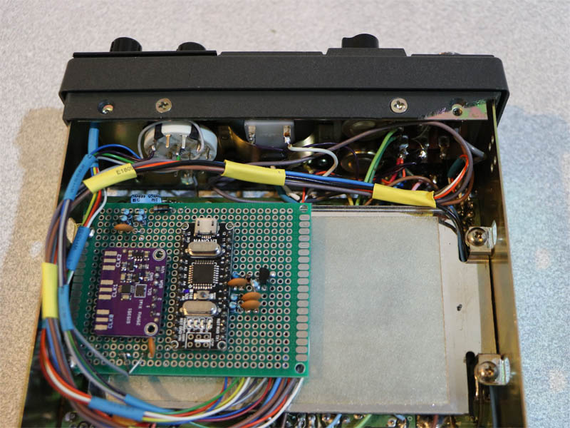
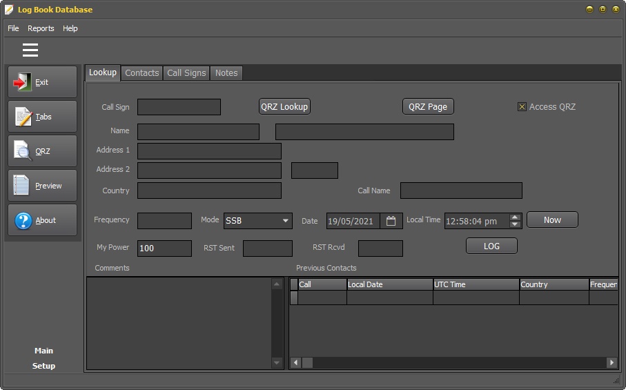
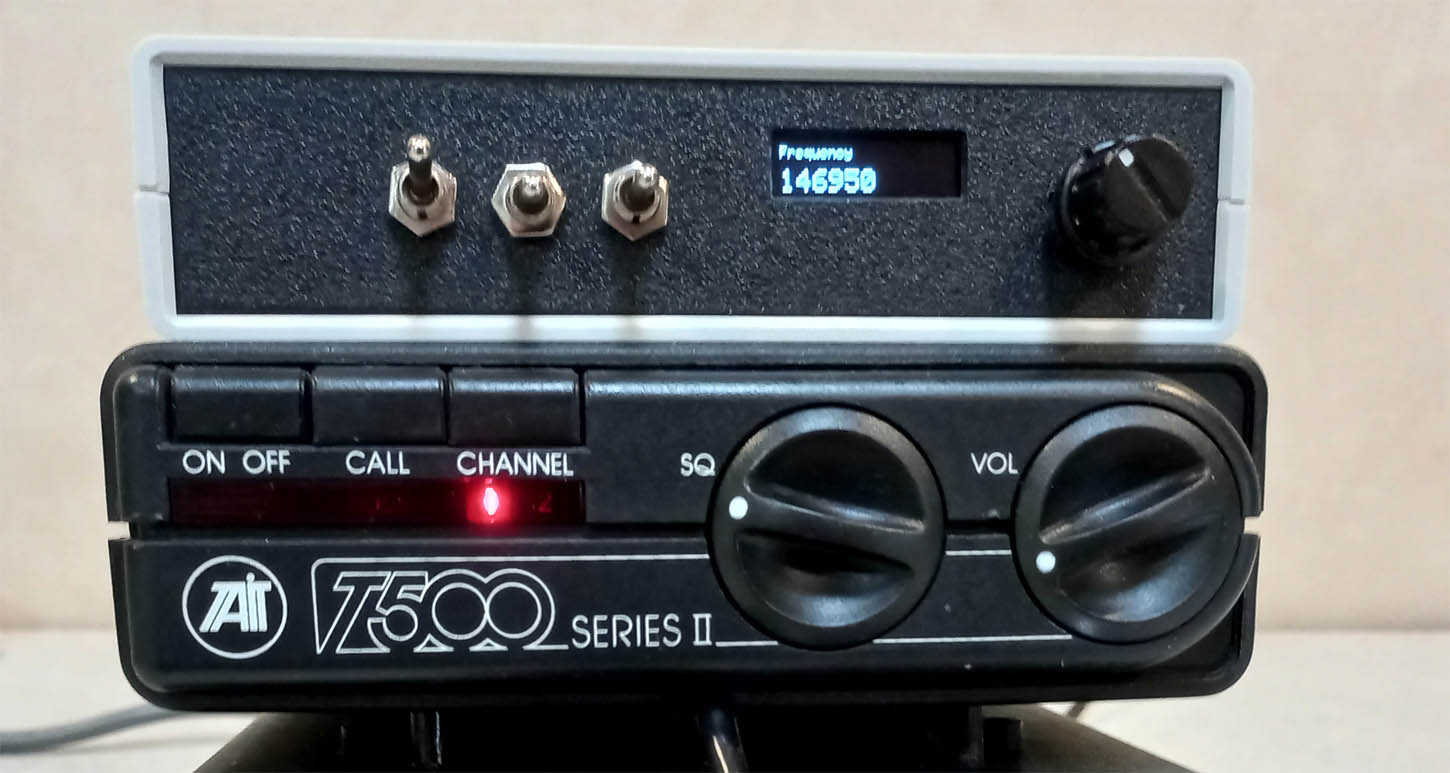
The DDS provides frequency selection by rotary encoder, repeater offset, memory storage and scanning. Downloads are provided for the circuit diagram and the code for the Arduino Micro used.

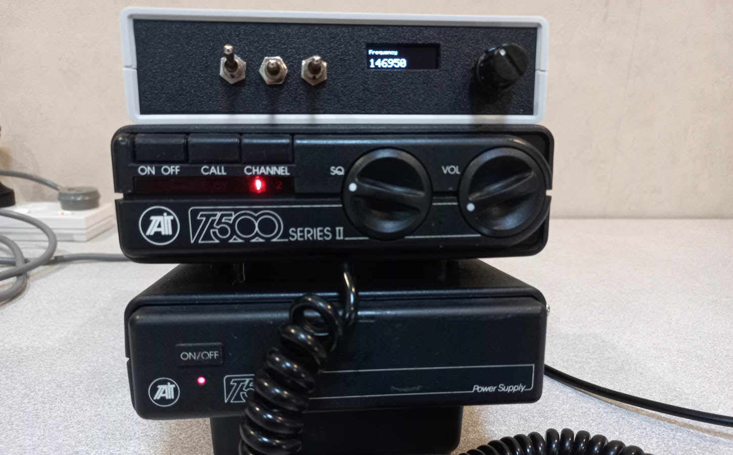
IC-22A before and after - uses an AD9850

IC-22S before and after - uses a Si5351

Front Panel

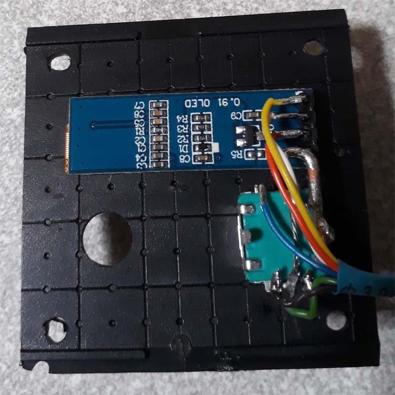
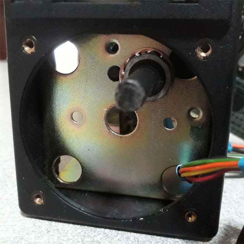
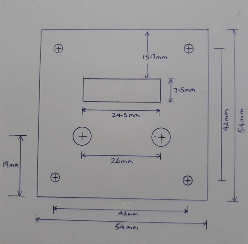
The front panel was made from the top of a HB6015 Jiffy Box available from Jaycar. The layout plan is a sketch and not to scale - dimensions need to be checked with the transceiver. I used a small router from AliExpress to cut the slot for the display but there are other ways to do that. Care is needed to drill the hole to mount the rotary switch on the transceiver. The rotary encoder is mounted on the plastic panel.

Download circuit and code as zip folder

Do note that the solution is not perfect. The DDS does have some spurious signals - 147600 and 146400 are particularly impacted on receive. Not likely to be much bother for most and it is still a heap better to be able to select operation anywhere on the band.  
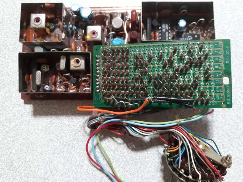
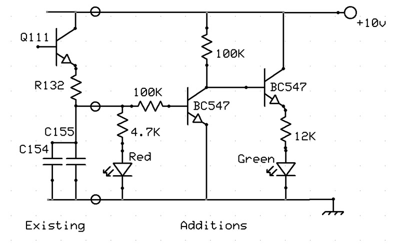
Note also to remove any capacitor between the base and emitter of the existing XTAL oscillator in the IC-22A and the IC-30A - we want that to now serve as an amplifier.  

Download circuit and code for the IC-30A

Like the IC-22 note that the solution is not perfect and has some spurious signals on receive. The physical layout and construction is the same as shown for the IC-22 transceivers but the circuit and code is different which is available in the download below.

COMPUTER LOG

There are a number of very complete software packages available for logging contacts but the packages I looked at seemed way too complex for what I wanted to do. So here is a very simple log book for the computer that has optional access to QRZ for callsign details. 
It is of course free and may be passed on to others but not sold. 
UPDATE - Now an updated version for 2023 which is essentially the same but with some improvements.  If you have a previous version your current data file should still work with this update.  
The software is designed for Windows 10 or Windows 11. Windows themes are available and as demonstrated in the images below you can set it to your own preference - Dark or Light and heaps of others between. 

Download Software as zip folder

Download the software as a zipped folder or just the Manual which is a .pdf file to get an idea of how it operates and what it is designed to do

SWR METER

This project uses an Arduino with CI-V codes to provide an analog meter for an ICOM IC-7300 Transceiver. The meter and enclosure is one that was intended for the YAESU FT-857 FT-897 and is readily available from AliExpress. The design available here enables reading Signal Strength, SWR and Power - other functions can be easily added. The download provides the code for the Arduino and a pdf file with construction photos and a brief description. 

Download Design as zip folder

SWR METER

This project uses an ESP32 and TFT display with CI-V codes to provide an analog meter for an ICOM IC-7300 Transceiver. The meter has a nice bright and clear display which I much prefer over a mechanical meter.  The design available here enables reading Signal Strength, SWR and Power - other functions can be easily added. The download provides the code for the ESP32 and a pdf file with construction photos and a brief description.  There is an additional download provided giving a later update with frequency and mode displayed below the S meter and a switched option for transmit display.

Download Design as zip folder

DELPHI WITH CI-V

Programming Delphi with CI-V Control. This software has been developed with Delphi to control an IC-7300 with CI-V commands over USB. This is intended as an example only of using CI-V control which may be of help if you want to develop your own software. The download includes some notes, Delphi source code and a compiled .exe which worked fine on my IC-7300.

Download Design as zip folder

TUNERS

Some trials of tuners on an IC-7300 that may be useful to some. I have an MFJ-2012 antenna. It is basically set up as an off centre fed dipole - a little bit inverted V. The IC-7300 internal tuner handled 40, 20, 10 and 6M fine but not the other bands. Four tuner purchases later I have settled on a mAT-180H auto tuner designed for the ICOM transceiver. Here is what I found with each tuner - did not include the 160M band.

MFJ-914

An extender for the internal tuner which performed really well. Didn't quite make the grade on part of the 80M band with my setup but was certainly doing what it was designed to do.

Kenwood AT-130

A really nice, small tuner. Really like this - it is small, has an analog meter, covers all I need and I rather like making the adjustments for best SWR. Only downside was trying to feed 50MHz directly through results in a spectacular pranging of the meter. Can switch it out if needs be.

ATU-100

Great little unit. Available as a kitset or fully built, inexpensive and covered really well. On auto it just tunes up and away you go. It does not store previous settings and does not integrate with the transceiver so a little bit of manual attention is necessary.

mAT-180H

They claim that it is fully compatible with ICOM AH-3 and AH-4 tuners. Never used the other tuners so I don't know - what I do know is that it integrates seamlessly with the IC-7300 and has expanded the matching capability from 80M up. Brilliant match and no messing around - press PTT, it tunes (if you have that transceiver option set) and away you go. If you want to tweak the SWR for a better result there are adjustments for that which can be saved. The tune button in the receiver works exactly as expected. One minor issue is that in my setup I switch the transceiver onto a dummy load when not in use with the tuner I/P and O/P disconnected. If you press tune with it like this it afterwards refuses to tune at all - even when reconnected. Power OFF then ON sorts that out. All in all it works so seamlessly and so well it is the one I have decided to keep using.

TAIT T500

The transceiver modified was diode programmable for two channels. Some solutions available to implement multiple channels involve programming the channels and an additional channel selector installation on the front panel.
The objective for this solution was to provide tuning across the whole 2M band without further programming. A unit was developed for this using an Arduino Nano.

Download Design as zip folder

TAIT T198

A DDS unit was fitted to a Tait T198 and the details may be downloaded here

Download circuit and code as zip folder

Do note that the solution is not perfect. The DDS does have some spurious signals - 147600 and 146400 are particularly impacted on receive. Not likely to be much bother for most and it is still a heap better to be able to select operation anywhere on the band.

FM Receiver

Basically a bit of a play around with FM Modules a TEA5767, SI4703 and a RDA5807. Also a programming exercise with an ESP32 micro.

Download Design as zip folder

YAESU FRG-7

I have restored several of these. The first one was in a right mess but I was amazed at the performance of these receivers. So it was sandpaper, paint, parts and modifications.

Transformed to this...

The front panel was in a terrible state so completely stripped that, sprayed firstly with an etch primer for aluminium and some layers of flat black paint+primer and relabelled using Letraset. Finally a clear coat to preserve the lettering. I have found the Rust-oleum Painters Touch+ spray can paint to be easy to use, doesn't clog or splatter and covers well. It is also reasonably well priced. Recoat within 30 minutes or after 48 hours - I got caught on the chassis - even after 48 hours in cold weather the first coat lifted when resprayed so make sure the first coat is thoroughly dry before applying a second. The Letraset I have is a very old set for electronic equipment - maybe others have some ideas on how to relabel a panel some other way. 
With health and safety the way it is I am very nervous about the safety of the mains wiring on these receivers. This receiver didn't even have a mains earth connection. The internal mains wiring seems to me to also leave a lot to be desired so I have removed the mains supply from the receivers I have worked on. There is a socket for a 12v supply on the rear panel so a 12v power adapter can be easily used. Older style adapters that use a transformer may be good but I found a number of adapters gave a lot of noise in the receiver. I found a 12v 1A adapter that is used on Huawei modems very quiet and worked well for this receiver. A good external aerial and earth is needed for these receivers.  Lots of capacitors needed to be changed, sockets and corroded parts replaced.

A common modification for these receivers is to change the lock light to show green on locked and red when unlocked which is much more intuitive than the original design. The modification of the lock light described here comes from other places on the net but the layout described here may be of use. Use a tri-colour LED which has a frosted lens. The clear lenses are way too bright and distracting.